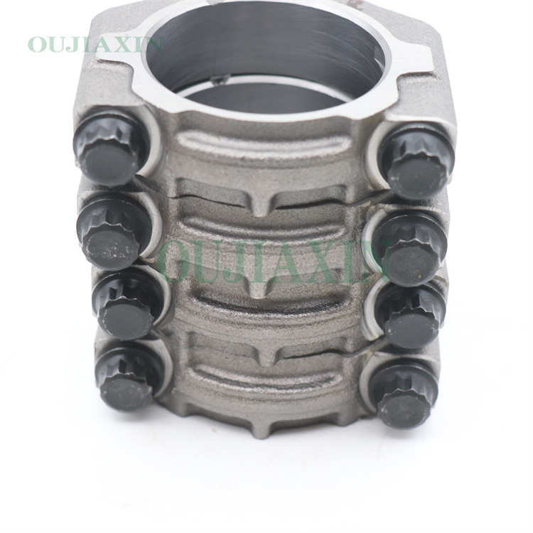
Connecting Rod Design Calculation
The connecting rod is the quiet hero in an engine, transforming an explosive heartbeat into smooth rotation. Its design calculation is a delicate balance between strength, lightness, and durability. A well‑designed rod minimizes weight without sacrificing reliability, and it does so by turning a cascade of measurements into a trusted component.

In practice, engineers follow a disciplined sequence of calculations to turn geometry into performance. The first step is geometry and kinematics: choose the rod length L and crank radius r, giving a L/r ratio that controls how much the rod tilts during rotation. This tilt determines the piston’s motion, the velocity and acceleration of the piston, and the instantaneous angle between the rod and the cylinder axis. A simple but essential outcome is the piston displacement as a function of crank angle, which informs the peak inertial loads the rod must carry.
Next comes load estimation. The gas pressure inside the cylinder pushes on the piston, producing a piston force Fp equal to pressure times piston area. The rod must transmit this force to the crank while also carrying the inertial forces of the moving piston and rings. Because the rod is angled during operation, the force in the rod, Frod, is larger than Fp by a factor roughly related to the rod angle: Frod grows as the rod becomes more oblique, especially near extreme crank positions. This step sets the peak stresses the cross section must withstand.
Then structure sizing and stress analysis. The rod experiences axial load plus bending due to its misalignment and the geometry of the pin joints. The cross section must resist axial stress (F_rod divided by the rod area) and bending stress (from the moment produced by the angled force along the rod). Designers check stress concentrations at the crankpin and the rod-cap joints, evaluate the combined stress state (often with fatigue criteria like Goodman or S-N curves), and apply a suitable safety factor to cover manufacturing variability, material imperfections, and load transients.
The final steps are fatigue life and practical optimization. Because the rod endures millions of high‑frequency cycles, fatigue resistance is often the controlling factor. Material choice (high‑strength steel alloys, sometimes lightweight aluminum or titanium), heat treatment, and geometric features (fillets, hole sizes, surface finish) all influence the durability. Designers also consider manufacturability and cost, ensuring the chosen L/r ratio, material, and cross section align with production capabilities and desired engine performance.
In a world of high RPMs and tight tolerances, a small miscalculation can ripple into failure. A robust connecting rod design calculation blends kinematics, forces, material science, and fatigue theory into a single objective: to deliver maximum power with minimum weight, every cycle, reliably.
Our products are exported to Germany, Russia, Brazil, Japan, the United States, and the Middle East. We are a trading company. We choose the most stable quality factories in China to cooperate with. We cooperate with 7,600 factories in China and sell 74,000 products each year. , we have 26,000 models in stock.